LMA-A
Description and Principle of Operation
The LMA-A lost model alarm is actively triggered, meaning an explicit servo control command is required to activate the alarm. This command is issued by the pilot operating the transmitter or by a receiver's fail-safe movement to a pre-programmed position in case of a lost radio connection. The triggering threshold position for the lost model alarm LMA-A is close to the neutral (center) point of a servo movement range (~1.5ms servo pulse length); any servo signal values bellow this mid-point of the servo movement range will activate the alarm; servo signal values above the mid-point will turn it off.
In cases where the receivers provide fail-safe features the LMA-A lost model alarm is better suited for fail-save receivers which can have the fail-safe positions programmed to a specific position. For receivers with a "hold position" fail-safe please consider the LMA-P passively triggered lost model alarm too.
Receivers without any fail-safe features will also trigger the alarm if no transmitter signal is present and no servo signal is passed onto the lost model alarm unit.
Set-up and Installation
Connect the LMA-A lost model alarm to any unused channel of your receiver that you can control with your transmitter - ideally the transmitter control for this channel is a two position switch, providing the on and off positions for the alarm. Sliders, pots and tri-state switches can be used too.
If your receiver fail-safe positions can be programmed and you wish to set a fail-safe position on your receiver for the LMA-A lost model alarm channel, please select a fail-safe position bellow the mid-point servo movement range.
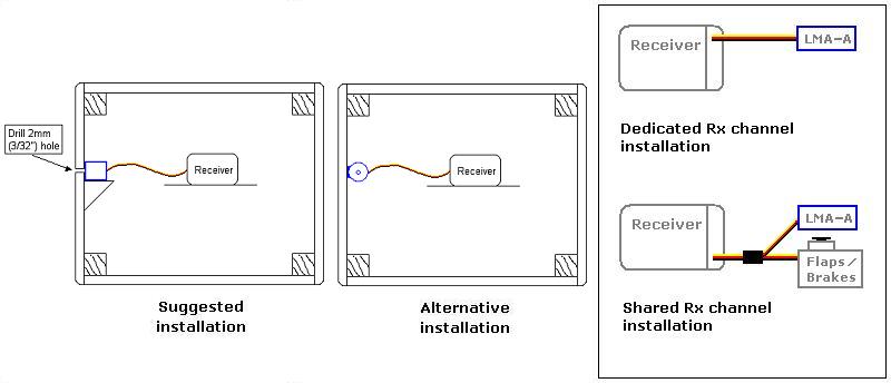
If a free receiver channel is not available the LMA-A lost model alarm can still be utilized by sharing a receiver's channel with some other intermittently used controls like landing gear, flaps or air-brakes. Use a Y-Splitter servo cable to connect the LMA-A lost model alarm to such a channel; the alarm will become active while the primary functions of the shared channel are invoked.
The preferred and more efficient installation of the LMA-A lost model alarm in your model suggests opening a small hole (~2mm) in the model walls and attaching the LMA-A lost model alarm so its sound emitting opening is aligned with this hole. Alternatively, secure the LMA-A lost model alarm in a suitable spot inside the model, check the sound. (please refer to the installation diagrams.) Depending on your model's structure the whole LMA-A lost model alarm can be completely exposed outside of the model too...
Powering the LMA-A
The LMA-A lost model alarm can be powered with power supplies ranging from 3V up to 9V. You can pretty much use any power source that your receiver/servos set-up can handle!
Example: You can use 4-cell or 5-cells NiCd/NiMH battery packs; or 1-cell or 2-cell LiPo/LiIon packs without exceeding the maximum voltage.These are thus suitable as a direct power source for the LMA-A lost model alarm.
Technical Characteristics
|
3V - 9V |
|
Less than 1mA silent at 5V Less than 20mA emitting sound at 5V (13mA typical at 5V) |
|
Minimum 85dB (90dB typical at 5V) at 10cm; 2300Hz |
|
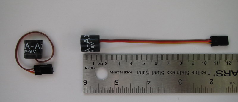
3.5g (including the servo wire and connector) |
|
Ø14mm x 14mm |
|
100mm |
|
Universal |
Demo Video
 |
See and hear the LMA-A lost model alarm in a short demo video on YouTube. |